
What Is a BMS Wire Harness and Why Is It Important?
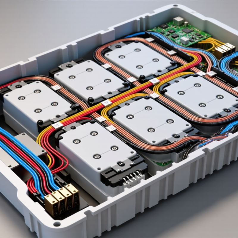
A Bms Wire Harness is the connected pathway between a battery pack and its management electronics. It carries power, voltage signals, temperature data, and balancing connections. Inside a typical pack, thin sensing wires run beside heavier current cables. Small connectors must remain secure despite vibration, heat, and repeated charging cycles.
It can seem simple. It is not. Engineers must match wire sizes, insulation materials, terminals, connector layouts, and protective sleeving to the battery’s operating conditions. A poorly routed harness may rub against a sharp enclosure edge. A loose terminal can create resistance, heat, and inaccurate measurements. These faults may reduce performance or trigger unwanted protection events.
The Bms Wire Harness also supports practical inspection and servicing. Clear labels, controlled bend radii, and consistent connector positions help technicians trace a fault without disturbing nearby cells. In production, documented tests such as continuity, insulation, and pull-force checks improve reliability. However, a test report cannot replace careful design review. Real packs face conditions that laboratory checks may not fully reproduce.
This component is often overlooked.
That is a mistake. The harness influences signal quality, thermal behavior, assembly time, and long-term safety. Experienced battery manufacturers treat it as part of the electrical system, not as ordinary cable. Material selection, routing, and connector quality should reflect the pack’s chemistry, current level, enclosure, and service environment. No design is perfect; every harness involves trade-offs. The important question is whether those choices are measured, documented, and suitable for the battery’s actual use.
What Is a BMS Wire Harness?
What Is a BMS Wire Harness?
A BMS wire harness is a structured group of wires, terminals, and connectors used in a battery management system. It links individual cells or cell groups with the BMS control board. Through these connections, the system measures cell voltage and monitors temperature. Some harnesses also carry signals for current sensing, balancing, and fault detection.
Small details matter. A typical harness may include closely spaced balance leads, temperature-sensor wires, locking connectors, and protective sleeving. Each lead must reach the correct measurement point. A misplaced wire can produce false readings or damage monitoring circuits. During assembly, technicians should check wire order, connector fit, crimp quality, and insulation condition. Testing continuity is useful. It is not enough.
A reliable BMS wire harness also manages movement and heat inside the battery enclosure. Proper strain relief prevents terminals from loosening during vibration. Clear labeling supports maintenance and reduces connection errors. Wire size depends on the signal or current involved, so one size cannot serve every circuit. In practical projects, a harness may look neat but still fail because of weak crimps or excessive bending. That is an easy issue to underestimate. Careful inspection, electrical testing, and documented assembly procedures improve confidence in long-term performance.
What Is a BMS Wire Harness and Why Is It Important?
| Data Dimension | Description | Typical Characteristics | Why It Matters |
|---|---|---|---|
| Definition | A BMS wire harness is an organized group of wires, terminals, connectors, and protective components used to connect a battery management system with a battery pack. | Designed for a specific battery layout, cell count, connector arrangement, and BMS configuration. | It provides the electrical paths required for monitoring, protection, balancing, sensing, and communication. |
| Cell-Tap Wires | Wires connected to the positive and negative terminals of individual cells or series groups. | The number of sensing wires generally corresponds to the number of monitored series groups plus the required pack reference connection. | They allow the BMS to measure individual group voltages and identify overvoltage, undervoltage, or imbalance conditions. |
| Temperature-Sensor Wires | Wires that connect thermistors or other temperature sensors to the BMS. | Common sensor types include negative-temperature-coefficient thermistors; the exact resistance rating depends on the BMS design. | Temperature feedback helps the BMS restrict charging or discharging when the battery is too hot or too cold. |
| Current-Sensing Connections | Connections for a shunt, Hall-effect sensor, or another current-measurement device. | The harness may carry low-level signal wires, power-supply wires, or both, depending on the sensing method. | Accurate current information supports state-of-charge estimation, fault detection, and charge or discharge control. |
| Balancing Connections | The same cell-monitoring leads may be used by the BMS to activate passive or active balancing circuits. | Passive balancing commonly dissipates excess energy as heat; active balancing transfers energy between cell groups. | Balancing helps reduce voltage differences between series groups and supports usable capacity and battery life. |
| Power and Ground Wires | Wires that supply the BMS electronics and provide the required reference or ground connection. | Wire size is selected according to operating current, voltage drop, temperature, insulation rating, and installation conditions. | Correct power connections help prevent unstable operation, overheating, incorrect measurements, and BMS failure. |
| Communication Wires | Wires used to exchange data between the BMS and external devices such as chargers, displays, controllers, or vehicle systems. | Common interfaces include CAN, UART, RS-485, and other manufacturer-defined communication links. | Reliable communication enables monitoring, configuration, diagnostics, and coordinated system control. |
| Connectors and Terminals | Mechanical and electrical interfaces that connect the harness to the BMS, cells, sensors, and other equipment. | Important specifications include pin count, terminal compatibility, contact rating, locking method, and environmental protection. | Correct connector selection reduces loose connections, reversed pins, signal errors, and accidental disconnection. |
| Insulation and Protection | Materials and structures that protect conductors from short circuits, abrasion, heat, moisture, and chemical exposure. | May include abrasion-resistant sleeving, conduit, shielding, strain relief, clips, labels, and insulation rated for the application. | Protection improves electrical safety, mechanical durability, serviceability, and resistance to environmental stress. |
| Wire Routing | The planned physical path followed by the harness inside or around the battery pack. | Routing should avoid sharp edges, high-heat areas, moving parts, excessive bending, and unnecessary proximity to high-current conductors. | Proper routing reduces vibration damage, electromagnetic interference, insulation wear, and installation errors. |
| Polarity and Pinout | The defined assignment of positive, negative, sensing, temperature, communication, and control connections. | Pin order must match the BMS and battery design; wire color alone should not be treated as a substitute for verification. | Incorrect polarity or pin placement can cause inaccurate readings, component damage, short circuits, or safety hazards. |
| Testing and Inspection | Verification of continuity, insulation, connector fit, pin sequence, sensor readings, and resistance to ground where applicable. | Testing should be completed before energizing the battery pack and repeated after installation or service. | Inspection helps detect open circuits, short circuits, reversed connections, damaged terminals, and incorrect assembly. |
| Overall Importance | The harness forms the connection layer between the battery pack and the BMS protection and monitoring electronics. | Its design must match the battery chemistry, series and parallel arrangement, maximum current, environment, and BMS requirements. | A correctly designed and installed harness supports battery safety, measurement accuracy, reliability, maintainability, and system performance. |
Note: Wire gauge, connector type, insulation rating, pinout, sensor specification, and protection requirements must be selected according to the specific battery pack and BMS documentation.