
How to Choose CNC Aluminum Profiles for Your Project?

Choosing the right Cnc Aluminum Profile is more than selecting a shape from a supplier catalog. It affects stiffness, machining time, assembly speed, surface finish, and long-term maintenance. In a real workshop, a profile that looks strong may still twist under an offset load. A lightweight section may save material, yet require extra brackets and labor. The correct decision connects the profile’s alloy, wall thickness, cross-section, tolerance, and joining method with the project’s actual working conditions.

Market data also explains why this choice deserves careful attention. Grand View Research estimated the global aluminum extrusion market at approximately USD 78.27 billion in 2023, with continued growth expected through 2030. The International Aluminium Institute reports that aluminum demand is closely linked to transportation, construction, and industrial manufacturing. These sectors increasingly value lightweight structures, corrosion resistance, and efficient fabrication. However, market growth does not make every extrusion suitable. A standard 6063 profile may provide an attractive finish, while a 6061 alloy can offer better mechanical performance after appropriate treatment. The difference matters.

Small details matter.

This guide examines how to compare profile geometry, alloy selection, load requirements, machining allowances, and surface treatments. It also considers supplier drawings, EN or ASTM references, and realistic tolerance expectations. Those documents improve reliability, but they are not perfect substitutes for testing. My practical view is simple: design calculations should guide the shortlist, while prototypes should challenge assumptions. A first design can be clean, economical, and still wrong. Careful selection begins when appearance gives way to measurable performance.
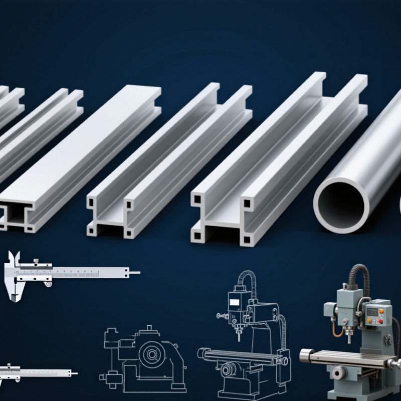
How to Choose CNC Aluminum Profiles for Your Project?

Define Loads, Span, and Tolerance Before Selecting an Aluminum Profile

How to Choose CNC Aluminum Profiles for Your Project?

Define loads, span, and tolerance before selecting an aluminum profile. This step prevents attractive designs from becoming weak assemblies.

Start by listing every load, not only the equipment weight. Include cables, moving parts, impact forces, and operator contact. A 500 mm span behaves differently from a 1,500 mm span. Longer spans usually need a larger section or additional support. Point loads also create more deflection than evenly distributed loads. Measure the actual load position. It matters.

Deflection often causes trouble before visible failure. For a frame carrying a linear guide, excessive bending can create alignment problems. Check bending, twisting, connection strength, and fastener pull-out. Use a reasonable safety factor, based on the application and verified calculations. An aluminum profile may look rigid, but thin walls and loose joints can reduce performance. I have seen projects blame the extrusion when the real weakness was an under-tightened corner connection. The calculation was correct. The assembly was not.

Set tolerances before machining or ordering profiles. Define hole positions, cut lengths, flatness, squareness, and sliding clearances. CNC machining can improve accuracy, but it cannot fix a poor tolerance plan.

Allow for thermal expansion when temperatures change across the frame. This detail is easy to overlook. It should not be. Recheck the design after adding covers, brackets, and cable carriers. Their weight may change the load path. A practical prototype can reveal assumptions that drawings hide.

Compare 6061-T6 Strength: 310 MPa Tensile and 276 MPa Yield

How to Choose CNC Aluminum Profiles for Your Project?

For many CNC frames, 6061-T6 offers a practical balance between strength, weight, and machinability. Its typical tensile strength reaches 310 MPa, while its yield strength is about 276 MPa. Tensile strength describes the point before fracture. Yield strength matters earlier because it shows when permanent bending begins. That difference is easy to overlook during profile selection.

Check the expected loads, unsupported length, and fastening method before ordering material. A long, thin profile may deflect even when its calculated stress stays below 276 MPa. I have seen brackets remain intact but shift enough to reduce cutting accuracy. That was not a material failure. It was a stiffness problem. Use thicker walls or add a cross brace where vibration appears.

Machining also affects the result. Sharp tools, stable clamping, and controlled feed rates help protect the profile’s geometry. Burrs around drilled holes can prevent full contact between mating parts. Clean the surface before assembly. Small gaps matter. Published strength values can vary with testing standards, section size, and heat treatment history. Confirm the mill certificate when the project carries significant loads. For critical structures, validate the design with calculations and a physical load test. My early estimates have sometimes looked convincing, then failed after real fasteners introduced uneven pressure. Recheck the details.

Evaluate Weight and Thermal Expansion at 2.70 g/cm³ and 23.6 µm/m·K

How to Choose CNC Aluminum Profiles for Your Project?

Evaluate Weight and Thermal Expansion at 2.70 g/cm³ and 23.6 µm/m·K

When selecting a CNC aluminum profile, begin with its mass, not only its appearance. Aluminum has a typical density of 2.70 g/cm³, making weight estimates fairly straightforward. Multiply the profile’s volume by this density, then include fasteners, brackets, wiring, and moving components. A lightweight frame may reduce shipping costs and motor loads. However, thinner walls can bend under vibration or uneven fastening. That trade-off deserves a real calculation.

Thermal movement also affects precision. With a coefficient of 23.6 µm/m·K, a one-meter profile can expand about 0.0236 mm for every 1°C rise. A 500 mm rail may move approximately 0.118 mm after a 10°C increase. That small change can affect sensor alignment, sliding motion, or machining accuracy. Allow clearance where parts must move, and use stable mounting points where alignment matters. Do not assume an indoor workshop has a constant temperature.

Check the alloy, temper, wall thickness, and supplier’s technical data before finalizing dimensions. Actual performance can differ from a basic estimate. In design reviews, I would test the longest section under expected loads and temperature changes. It is easy to focus on weight and overlook expansion. That mistake is common. A quick calculation helps, but it should not replace a prototype or measured inspection.

Match Profile Geometry, Wall Thickness, and ASTM B221 Requirements

How to Choose CNC Aluminum Profiles for Your Project?

Selecting a CNC aluminum profile starts with geometry, not appearance. Choose T-slots for modular frames and closed sections for higher torsional stiffness. A wide flange can reduce bending under load, but it may increase machining time. Keep unsupported spans short. They matter.

Wall thickness affects strength, weight, and cutting stability. Thin walls can deform during clamping, especially near pockets or drilled holes. Thick walls provide better thread engagement and heat control, but they add material cost. The U.S. Geological Survey’s Mineral Commodity Summaries 2025 estimated global primary aluminum production at about 72 million metric tons in 2024. This scale supports supply, but it does not guarantee the correct alloy or temper.

For documented quality, request certification to ASTM B221 for extruded aluminum profiles. The standard covers chemical composition, mechanical properties, and dimensional requirements for applicable products. Confirm the alloy, temper, tensile strength, yield strength, elongation, and dimensional tolerances on the mill certificate. Match these values with your design loads and machining plan. The International Aluminium Institute states that recycled aluminum uses roughly 5% of the energy required for primary production. That benefit is useful, but recycled content can vary. I would not assume identical machinability without verification. Ask for test results, inspect wall uniformity, and run a small machining trial before approving full production.

How to Choose CNC Aluminum Profiles for Your Project? - Match Profile Geometry, Wall Thickness, and ASTM B221 Requirements

Profile Geometry Typical Starting Size Indicative Wall Thickness Strength and Stiffness Considerations Suitable CNC Operations Common Alloy and Temper Options ASTM B221 Specification Check
Solid rectangular bar Width: 20–150 mm
Height: 10–80 mm
Not applicable; solid section High material concentration and predictable machining behavior. Larger sections provide greater bending resistance but add weight and material cost. Facing, pocketing, drilling, tapping, contour milling, and precision machining of mounting blocks. 6061-T6 for general structural machining; 6082-T6 where commonly specified by the supply chain. Specify alloy, temper, cross-sectional dimensions, length, dimensional tolerances, and required certification to ASTM B221.
Square or rectangular hollow profile Outside width: 20–100 mm
Outside height: 20–100 mm
1.5–5.0 mm as an initial design range Efficient stiffness-to-weight ratio. Corner radii reduce stress concentration and improve extrusion reliability; unsupported broad faces may flex during clamping. End machining, slotting, drilling, tapping, profile contouring, and pocket machining with internal support where needed. 6063-T5 or 6063-T6 for architectural and light-duty sections; 6061-T6 for higher-strength machined components. Confirm that the hollow shape, wall variation, corner radius, straightness, and dimensional tolerances are covered by the purchase specification and current ASTM B221 edition.
Round tube Outside diameter: 20–100 mm 1.5–6.0 mm as an initial design range Good torsional efficiency and uniform load distribution. Select a thicker wall for threaded holes, bearing seats, or repeated clamping. Turning, boring, drilling, cross-holes, end facing, thread machining, and radial slotting. 6061-T6 for structural and machined tube applications; 6063-T5/T6 for readily extruded general-purpose tube. Identify whether the product is an extruded tube or profile, then verify alloy, temper, outside diameter, wall thickness, length, and applicable dimensional tolerances.
L-angle profile Legs: 20–100 mm
Equal or unequal legs
2.0–8.0 mm as an initial design range Useful for brackets and edge reinforcement. The unequal-leg direction and fillet radius strongly affect bending performance and part location. Milling, drilling, countersinking, end trimming, notching, and hole-pattern machining. 6061-T6 for load-bearing brackets; 6063-T5/T6 for lighter frames and trim components. State leg dimensions, thickness, inside and outside radii, straightness requirements, alloy, temper, and ASTM B221 compliance.
T-slot framing profile Nominal grid sizes: 20, 30, 40, or 45 mm
Actual dimensions depend on the extrusion design
Approximately 1.5–3.5 mm on load-bearing webs Slots enable adjustable assembly, but slot openings reduce local section strength. Select a larger profile for long spans, heavy equipment, or high joint loads. Cutting, end tapping, drilling, slot enlargement, connector pockets, and face machining. 6063-T5/T6 is widely used for general extrusion framing; use a higher-strength alloy only when the design and supply specification support it. Do not assume a commercial slot standard is automatically ASTM B221 compliant. Specify alloy, temper, profile drawing, tolerances, and certification requirements explicitly.
U-channel profile Width: 20–120 mm
Leg height: 10–80 mm
2.0–6.0 mm as an initial design range Suitable for guides, covers, rails, and supporting channels. Open sections twist more easily than closed sections and may require bracing. Slotting, drilling, end milling, notching, countersinking, and mounting-hole machining. 6063-T5/T6 for formed channels and general-purpose components; 6061-T6 for higher-strength machined supports. Define channel width, leg height, thickness, radii, twist, straightness, alloy, temper, and ASTM B221 dimensional requirements.
Heat-sink profile Base width: 30–150 mm
Fin height: 10–60 mm
Base: 2.0–8.0 mm
Fin: commonly 0.8–2.5 mm
Thermal performance depends on fin height, fin spacing, airflow, surface area, and base flatness. Thin fins require careful clamping and handling. Base facing, mounting holes, threaded holes, end trimming, groove machining, and flatness-critical finishing. 6063-T5/T6 is commonly selected for extrudability and thermal applications; confirm the required temper and thermal design assumptions. Specify profile drawing, fin and base dimensions, alloy, temper, surface condition, flatness, dimensional tolerances, and ASTM B221 certification.
Custom multi-void profile Envelope: approximately 30–200 mm
Custom cross-section
Usually 1.5–5.0 mm; confirm manufacturability with the extruder Can integrate guides, cable passages, fastener bosses, and stiffening ribs. Highly asymmetric sections may distort or twist during extrusion and heat treatment. CNC datum creation, drilling, tapping, pocketing, end features, and close-tolerance interface machining. Alloy and temper should be selected from the required strength, corrosion resistance, extrusion complexity, and machining needs; 6061-T6 and 6063-T5/T6 are common starting points. Provide a controlled drawing with alloy, temper, section dimensions, wall limits, radii, length, tolerances, inspection method, and ASTM B221 requirements. Custom geometry should be reviewed before ordering.
Selection note: The size and wall-thickness ranges above are practical preliminary design ranges, not universal minimums or maximums. Final limits depend on the alloy, temper, profile complexity, extrusion capability, CNC clamping method, loading conditions, and applicable ASTM B221 dimensional-tolerance tables. Request the current material certificate and verify the exact alloy, temper, dimensions, tolerances, and inspection requirements before production.

Verify CNC Accuracy, Surface Finish, and ISO 2768 Tolerances

How to Choose CNC Aluminum Profiles for Your Project?

CNC accuracy should match the function of your aluminum profile, not only its appearance. Check critical dimensions, hole positions, flatness, and perpendicularity on the engineering drawing. A profile may look precise but still misalign during assembly. Request an inspection report with actual readings, measurement tools, and calibration dates. For tight features, a coordinate measuring machine provides stronger evidence than a basic caliper.

Surface finish also needs a clear definition. “Smooth” is not a measurable requirement. Specify machining marks, allowable scratches, edge treatment, and the required roughness value, such as Ra, where applicable. Inspect sample parts under consistent lighting. Fingerprints can hide small defects. They should not. An anodized or coated surface may improve appearance, but it cannot correct poor machining accuracy underneath.

ISO 2768 can provide general tolerances when individual dimensions lack limits, but it does not replace critical tolerances on the drawing. Confirm whether the project uses fine, medium, or coarse tolerance classes. Match that class to the profile’s purpose and manufacturing process. Extruded sections may shift slightly before machining, especially over long lengths. This is easy to underestimate. Review first-article results before approving full production. If a dimension repeatedly approaches its limit, revise the process or drawing rather than accepting optimistic assumptions.