
How to Choose a Grounding Transformer?
Choosing a Grounding Transformer is a protection decision, not merely a purchasing exercise. It affects fault-current paths, insulation stress, relay coordination, and system continuity. The International Energy Agency’s Electricity 2024 report projects global electricity demand to rise by about 4% annually through 2026. More generation and network expansion create more applications for reliable neutral grounding.
The details matter. A transformer for a 13.8 kV industrial bus may require different zero-sequence impedance than one serving a renewable-energy collector system. Engineers should check system voltage, grounding method, fault duration, neutral current, thermal capacity, insulation level, and installation altitude. IEEE Std 32 and IEC 60076-6 provide useful technical references for grounding transformers and associated reactors. The U.S. Department of Energy’s National Transmission Needs Study also highlights growing transmission constraints, reinforcing the need for coordinated protection design.
Lewis Blackburn, a widely cited protective-relaying authority, stated that grounding should “limit the duration and magnitude of overvoltages.” That principle remains practical beside a switchgear lineup, where a wrong neutral connection can increase damage within cycles. Still, no selection formula works perfectly. Fault studies may use uncertain utility data, changing inverter behavior, or incomplete cable information. That weakness deserves attention. A sound review compares zigzag and wye-delta designs, verifies manufacturer test results, and confirms the transformer’s duty under real fault conditions. The best Grounding Transformer is not always the largest unit. It is the one that matches the network’s electrical behavior, protection scheme, and future operating changes.
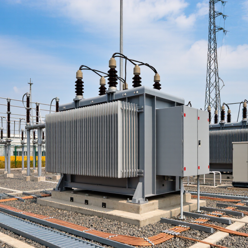
Grounding Transformer Fundamentals and Operating Principles
How to Choose a Grounding Transformer?
Grounding transformer fundamentals begin with one purpose: creating a stable neutral point. This matters on delta or otherwise ungrounded systems. During a line-to-ground fault, the transformer provides a controlled zero-sequence path. Its design limits overvoltage and gives protection relays a detectable fault current.
Common designs include zigzag and wye-delta transformers. A zigzag unit often fits compact medium-voltage substations. A wye-delta design may suit systems requiring stronger phase-shifting performance. Select the neutral grounding resistor or reactor with care. The target fault current must balance relay sensitivity, equipment damage, and touch-voltage risk. IEEE Std 32 addresses neutral grounding devices, while IEC 60076-6 covers reactor-related requirements. These documents support engineering decisions, but they do not replace a site study.
Grid conditions are changing. The IEA Electricity 2024 report expects global electricity demand to grow by an average 4% annually through 2026. More distributed generation can make fault behavior less predictable. A grounding transformer should therefore be checked against inverter controls, cable capacitance, short-circuit duty, and continuous neutral loading. A neat calculation is not always enough. Field measurements may reveal assumptions that the model missed.
Tips: Confirm the required zero-sequence impedance. Check the short-time thermal rating, usually tied to the protection clearing time. Verify relay coordination with real fault-current values. Leave room for future feeders. And document the grounding method clearly; technicians may interpret vague drawings differently.
System Requirements for Selecting a Grounding Transformer
How to Choose a Grounding Transformer?
System Requirements for Selecting a Grounding Transformer
Selecting a grounding transformer starts with the system, not the equipment catalog. Confirm the nominal voltage, frequency, phase arrangement, and available fault current. The transformer must match the system’s insulation level and connection method. A zigzag unit may suit a system needing a neutral point, while a delta-wye design can provide isolation and auxiliary power. The choice depends on the network.
Define the grounding objective clearly. Some installations need a low-impedance path for high fault current. Others require resistance grounding to limit damage and arc energy. Specify the intended fault current and its duration, such as 10 seconds or continuous service. Check neutral displacement, relay sensitivity, and coordination with upstream protection. Small calculation errors matter. The first estimate is rarely perfect.
Thermal performance also needs practical attention. Review ambient temperature, altitude, enclosure ventilation, harmonics, and duty cycles. A transformer exposed to dust or outdoor moisture may need stronger enclosure protection. Confirm short-time withstand ratings with the protection study, not only the nameplate. Applicable electrical codes and site standards should guide the final design. A qualified engineer should verify the grounding resistor, conductor size, and touch-voltage limits. Field conditions often differ from drawings. That is where careful review becomes essential.
Grounding Transformer Types and Configuration Options
How to Choose a Grounding Transformer?
Grounding transformer selection starts with system behavior, not catalog size. Zig-zag transformers suit networks needing a neutral point with limited physical space. Their winding arrangement provides a path for zero-sequence current while reducing normal-load interference. Wye-delta units offer stronger isolation and can support auxiliary loads. The delta winding also helps contain triplen harmonics. Resistance and reactance grounding are configuration choices, not separate transformer types. They control fault current, touch voltage, and relay sensitivity.
EIA’s 2024 Annual Energy Review reports roughly 660 billion kilowatt-hours from U.S. wind and utility-scale solar generation in 2023. More inverter-based generation can reduce available fault current. NERC’s 2024 State of Reliability also identifies inverter-based resource performance as an increasing grid concern. Therefore, engineers should verify protection performance under both strong-grid and weak-grid conditions. A 13.8-kilovolt system limited to 400 amperes needs about 19.9 ohms of resistance, using the 7.97-kilovolt phase voltage. Real projects still require fault studies.
Check continuous current, short-time thermal duty, zero-sequence impedance, insulation level, and neutral resistor rating. IEC 60076-6 addresses reactor-type transformer requirements, while IEEE Std 32 covers neutral grounding devices. A ten-second rating may work for one protection scheme, but not another. I have seen neat spreadsheets hide poor relay coordination. Field measurements can disagree with assumptions. That is uncomfortable, but useful. Pay attention to harmonics, cable capacitance, grounding electrode resistance, and future feeder additions before approving the configuration.
How to Choose a Grounding Transformer? - Grounding Transformer Types and Configuration Options
| Transformer Type | Typical Connection | Main Function | Recommended System Arrangement | Advantages | Limitations |
|---|---|---|---|---|---|
| Zigzag Grounding Transformer | Three-phase zigzag winding with a neutral terminal | Creates an artificial neutral and provides a low-impedance path for zero-sequence current | Ungrounded or delta-connected medium-voltage systems requiring a neutral grounding point | Compact design, efficient zero-sequence performance, and no secondary load winding required | Does not normally supply useful continuous secondary power; grounding impedance must be correctly specified |
| Wye-Delta Grounding Transformer | Primary wye connection with an accessible neutral and secondary delta winding | Provides system grounding and may supply auxiliary three-phase power | Systems where grounding and a dedicated auxiliary power source are both required | Offers a neutral grounding point and a secondary output in one transformer | Generally larger and more expensive than a grounding-only zigzag unit; secondary loading affects thermal sizing |
| Wye-Wye Grounding Transformer | Grounded wye primary and wye secondary, subject to the required zero-sequence design | Provides grounding and voltage transformation where a neutral-to-neutral arrangement is suitable | Specialized installations with compatible neutral and zero-sequence requirements | Can provide an auxiliary output with a straightforward phase-to-neutral arrangement | May require careful zero-sequence and harmonic analysis; not the default choice for every ungrounded system |
| Grounding Transformer with Neutral Grounding Resistor | Transformer neutral connected to ground through a resistor | Limits earth-fault current to a controlled value while allowing protective relays to detect faults | Medium-voltage systems requiring reduced fault damage and selective ground-fault protection | Controls fault current, reduces arc-flash energy compared with solid grounding, and improves relay coordination | The resistor must be thermally and electrically rated for the specified fault duration |
| Grounding Transformer with Neutral Grounding Reactor | Transformer neutral connected to ground through an inductive reactor | Restricts ground-fault current using inductive reactance | Installations where a reactor-based grounding method is compatible with protection and transient requirements | Can limit fault current without dissipating the same level of active power as a resistor | May increase transient overvoltage risk if improperly applied; system capacitance and resonance require evaluation |
| Grounding Transformer with Solid Neutral | Transformer neutral directly bonded to the grounding grid | Provides a low-impedance ground-fault path and fast fault-clearing conditions | Systems designed for high ground-fault current and rapid operation of overcurrent protection | Simple design and strong voltage reference during ground faults | High fault current can increase equipment stress, arc-flash energy, and conductor damage |
Key Configuration Parameters
| Selection Dimension | Common Options | What to Check | Effect on the Design |
|---|---|---|---|
| System Voltage | Low voltage, medium voltage, or high voltage | Line-to-line voltage, insulation level, temporary overvoltage, and applicable standards | Determines winding insulation, clearances, bushings, and test requirements |
| Ground-Fault Current | Solidly grounded, low-resistance grounded, or high-resistance grounded | Required fault current, protection sensitivity, and maximum clearing time | Sets the transformer zero-sequence impedance and the resistor or reactor rating |
| Continuous Rating | Grounding-only duty or grounding plus auxiliary load duty | Continuous neutral current, auxiliary kVA, load profile, and ambient temperature | Determines thermal capacity and whether a secondary winding is required |
| Short-Time Rating | Typical protection clearing intervals such as 10 seconds or 30 seconds | Fault duration, repetition, thermal withstand, and mechanical withstand | Defines the permissible fault current and duration without damaging the transformer |
| Neutral Grounding Method | Solid connection, resistor, reactor, or grounding electrode system | Protection philosophy, touch voltage, arc-flash objectives, and system capacitance | Controls fault magnitude, transient behavior, and relay coordination |
| Insulation and Environment | Indoor or outdoor; dry-type or liquid-immersed; standard or harsh environment | Altitude, humidity, pollution, corrosion, fire requirements, and cooling conditions | Affects enclosure rating, cooling method, insulation coordination, and maintenance needs |
| Protection and Monitoring | Neutral current transformer, resistor monitoring, temperature sensors, and surge protection | Ground-fault relay settings, alarm requirements, communications, and test access | Improves fault detection, maintenance planning, and operational safety |
Key Ratings and Protection Factors to Evaluate
Choosing a grounding transformer requires more than matching system voltage. The neutral must withstand the expected zero-sequence current, fault duration, and thermal stress. IEEE Std 32 and IEC 60076-6 provide practical guidance for grounding transformer and neutral grounding equipment ratings. A 10-second neutral current rating is common in industrial designs, but it is not a universal default. Confirm the actual clearing time with the protection study.
Evaluate insulation level, continuous neutral current, short-time current, and impedance together. A low impedance may limit voltage rise, yet it can increase fault current beyond switchgear capability. The transformer must also tolerate temporary overvoltage during earth faults. NERC’s 2024 State of Reliability report continues to identify protection misoperations as a recurring transmission reliability concern. That finding matters here: incorrect CT ratios, relay settings, or grounding assumptions can defeat an otherwise strong transformer design. Small errors become expensive during a fault.
Tips: Request zero-sequence impedance, thermal withstand, and neutral-point test data. Check whether the resistor is rated for 10, 30, or 60 seconds. Compare this duration with the relay clearing time, not the breaker nameplate alone. CIGRE Technical Brochure 739 also supports reviewing grounding behavior across normal and abnormal operating conditions. Do not rely only on a catalog rating. Field measurements may reveal harmonic current, unbalanced loading, or a shorter fault duration than the original study assumed. I have seen calculations look complete while missing the cable screen path. That detail deserves another review.
Installation, Testing, and Maintenance Considerations
How to Choose a Grounding Transformer?
Installation, Testing, and Maintenance Considerations
A grounding transformer should match the system voltage, fault current, and grounding duration. IEEE 142 recommends evaluating zero-sequence impedance before final selection. This value controls fault-current behavior and neutral stability. Do not choose from kVA alone. A small calculation mistake can overheat the neutral path.
During installation, verify phase sequence, enclosure bonding, cable clearances, and neutral connections. The U.S. Department of Energy reports that large transformers commonly remain in service for about 40 years, so installation defects can create long-term risk. Use IEEE 81 methods to measure soil resistivity and grounding resistance. Record weather, electrode spacing, and test instrument details. Wet soil may produce a misleadingly favorable result.
Testing should include insulation resistance, winding resistance, ratio checks, and zero-sequence impedance verification. NETA MTS 2023 emphasizes comparing results with factory data and previous records, rather than relying on one pass-or-fail number. Thermal scanning under load can reveal loose terminals. It is simple, but often skipped. NFPA 70B supports documented electrical maintenance programs and condition-based decisions. Inspect connections for corrosion, cracked insulation, water entry, and unusual noise. Review test trends annually. I would not treat one acceptable reading as proof of health; temperature, moisture, and loading can change the evidence.
How to Choose a Grounding Transformer: Installation, Testing, and Maintenance
The chart presents a practical planning cadence for common grounding-transformer activities. Installation checks and commissioning tests are completed before energization, while routine inspections are commonly planned annually and detailed condition assessments at longer intervals. Actual schedules should follow the transformer design, duty cycle, environmental conditions, local regulations, and the manufacturer’s instructions.
