What Is a Ring Main Switch and How Does It Work?
A Ring Main Switch is a compact switching device used to control, isolate, and protect electrical circuits within a ring-shaped distribution network. In medium-voltage systems, it commonly forms part of a ring main unit, connecting transformers, feeders, and substations. The arrangement allows power to reach equipment from different directions. If one cable section fails, operators can isolate that section and restore supply through the opposite route.
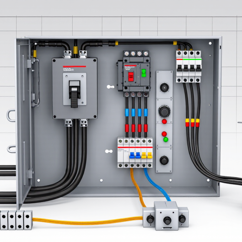
The hardware looks orderly inside a metal enclosure. You may find load-break switches, circuit breakers, earthing switches, busbars, and protection controls. Each component has a specific duty. The load-break switch controls normal current, while the earthing switch helps make isolated conductors safe for maintenance. It is not a simple household switch. Fault levels, insulation, operating mechanisms, and interlocking systems require careful engineering.
Mike Holt, a respected electrical educator, warns, “Electricity doesn’t care if you’re qualified or not.” That warning applies directly here. A Ring Main Switch must be selected, installed, tested, and operated by competent professionals. Small mistakes can create severe arc-flash or equipment hazards.
This guide explains how the switch works, where it fits in a distribution system, and why protection settings matter. It also separates ring main switchgear from domestic ring circuits, which are often confused. The distinction is important. A diagram may look simple, yet real installations involve cable ratings, fault-current calculations, earthing design, and local regulations. Some explanations make the equipment sound foolproof. It is not. Good engineering still depends on accurate data, disciplined procedures, and regular inspection.
What Is a Ring Main Switch?
A ring main switch is a medium-voltage switching device used in electrical distribution networks. It connects, isolates, or redirects power within a ring-shaped feeder system. The ring allows electricity to reach a transformer from different directions. If one cable section develops a fault, operators can isolate that section and restore supply through the other route.
The switch is usually installed inside a ring main unit, alongside circuit protection and earthing equipment. During normal operation, its contacts carry the feeder current. When opened, the contacts separate and create a visible or verified isolation point. Some designs use vacuum interruption, while others use sealed insulation systems. The exact construction depends on voltage, fault level, and local installation standards.
In practical maintenance, technicians confirm the circuit identity before operating the switch. They check voltage indicators, follow the switching schedule, and apply an earth connection when required. That matters. A switch may appear open while another source still energizes part of the network. The term “ring” can also confuse new readers, because the circuit does not always operate as a closed loop. Operators often keep one point open to control power flow and limit fault current.
A reliable ring main switch must provide safe load switching, clear position indication, and dependable mechanical interlocking. It is not simply a large on-off button. Its design, testing, and operation require trained personnel and site-specific procedures.
Key Components and Their Functions
What Is a Ring Main Switch and How Does It Work?
A ring main switch controls medium-voltage power flowing through a looped distribution network. Its main parts include the switch-disconnector, busbars, cable terminations, earthing switch, and protective device. The switch-disconnector opens or closes the circuit during normal operation. It is not always designed to interrupt severe fault currents. That task belongs to a fuse or circuit breaker. The earthing switch connects isolated conductors to ground, reducing stored electrical risk during maintenance. Mechanical interlocks prevent unsafe sequences, such as closing the earth switch onto a live feeder.
Inside the enclosure, busbars carry power between incoming and outgoing feeders. Cable compartments guide connections and support insulation clearances. A gas, air, or solid-insulated chamber separates live components from operators. The International Energy Agency reported that global electricity demand increased by 2.2% in 2023 and expects average annual growth of 3.4% from 2024 to 2026. This growth makes dependable distribution equipment increasingly important. IEC 62271 requirements help engineers assess medium-voltage switchgear performance, insulation, and switching duties. Still, a simple diagram can hide difficult site conditions. Moisture, dust, poor cable stress control, or incorrect interlock settings can weaken protection.
Tips: Check the position indicator, test mechanical interlocks, and inspect cable terminations during commissioning. Record torque values and insulation-test results. Never trust an indicator alone. A visible isolation point and a verified earth connection matter more than routine assumptions. Cite: IEA, Electricity 2024; IEC 62271 series.
How a Ring Main Switch Operates
What Is a Ring Main Switch and How Does It Work?
A ring main switch controls power supplied to a ring final circuit. This circuit carries electricity around a continuous loop, with outlets connected along the route. The switch usually sits inside a consumer unit or distribution board. It connects or separates the circuit from the supply.
How a Ring Main Switch Operates
When the switch is on, its internal contacts close and allow current to flow through the ring. Electricity can travel in both directions around the loop, helping distribute the load between the conductors. When the switch is off, the contacts open and interrupt the circuit. A visible handle gives the user a clear isolation point.
The switch itself may not provide overload protection. A separate protective device normally detects excessive current or a short circuit, then disconnects the circuit automatically. This distinction matters during inspection and repair. A qualified electrician should isolate the supply, lock it where appropriate, and confirm dead with a tested instrument before touching conductors. Never rely only on the switch position.
In practice, terminology varies between electrical systems. Some diagrams show a switch disconnecting live conductors, while others use combined switching and protection. The arrangement should match local wiring rules and the equipment’s rating. I have found that unclear labels create avoidable mistakes. A circuit schedule, test results, and careful visual checks offer better evidence than assumptions.
Protection and Fault Isolation in Ring Networks
A ring main switch connects distribution feeders into a closed loop, usually within a medium-voltage network. Power can enter from either direction. If one cable section fails, operators open two switches around the fault and restore supply from the opposite side. The faulty section stays isolated while healthy customers remain energized. It is a practical form of protection and fault isolation, not simply a larger circuit breaker.
Modern ring main units combine load-break switches, fuses, circuit breakers, and earthing switches. Protection relays detect overcurrent or earth faults, then send a trip signal within milliseconds. Operators may also use indicators, remote controls, and cable test points. The IEA Electricity 2024 report expects global electricity demand to grow by about 6% between 2023 and 2026. More demand makes dependable feeder switching increasingly important. The U.S. Energy Information Administration has reported roughly six outage hours per customer in recent annual data, including major events. Isolation speed can therefore affect real service performance.
Correct coordination matters. A fuse that trips too early may disconnect an unnecessary section. A relay set too slowly may allow cable damage. IEC 62271-200 addresses metal-enclosed switchgear requirements, while IEC 62271-103 covers high-voltage switches. Field teams still need clear labels, tested interlocks, and verified protection settings. A drawing can look perfect. The cabinet may tell another story. Moisture, aging mechanisms, or a missed cable route can defeat a sound design. That uncomfortable gap deserves regular inspection and honest review.
Common Applications and Maintenance Requirements
A ring main switch is a medium-voltage device used to control and protect electrical distribution networks. It connects incoming and outgoing cables in a ring arrangement, allowing electricity to reach a substation from different directions. If one cable develops a fault, operators can isolate that section while keeping other areas supplied. This makes ring main switches useful in commercial buildings, residential developments, industrial sites, and renewable energy installations.
Maintenance requirements depend on the switch design, insulation method, operating frequency, and local electrical rules. Technicians should inspect enclosure condition, cable terminations, mechanical interlocks, earthing points, and indicator accuracy. Unusual noise, corrosion, moisture, or stiff operating handles require attention. Insulated systems may also need pressure or leakage checks, while older equipment can require additional testing. Always de-energize and verify isolation before inspection. A checklist helps, but it is not foolproof. Human error remains possible.
Tips: Keep access areas dry and unobstructed. Record every operation, inspection, and fault indication. Exercise manual mechanisms only under approved procedures. Do not force a handle or bypass an interlock. Maintenance intervals should follow the equipment manual, site risk assessment, and qualified electrical supervision. In practice, rushed inspections often miss loose connections or damaged seals. Slower checks are usually safer.